

Megasonic Wafer Cleaning System Vendor Guide for High-Precision Semiconductor Processes
2026-10-30
Precision cleaning at sub-100nm nodes isn't a luxury—it's the difference between yield and scrap. Yet most megasonic wafer cleaning guides read like generic spec sheets. This one doesn't. We've distilled what actually matters when selecting a megasonic system for high-precision semiconductor processes: cavitation control, frequency uniformity, chemical compatibility, and process repeatability. Siansonic has spent years tuning these parameters for advanced fabs, and this guide shares the hard-won insights. If your current cleaning step is leaving particles behind—or damaging fragile structures—read on.
Reading Between the Lines of Megasonic Spec Sheets
Megasonic spec sheets often lead with frequency and wattage, but those headline numbers rarely reflect actual cleaning behavior. Two systems rated at 1 MHz and the same power can behave completely differently depending on transducer array geometry, coupling layer thickness, and how energy is distributed across the tank. A closer look at power density per unit area, and how that maps against the transducer footprint, tells you more than the wattage sticker ever will.
Another detail that gets buried is the difference between electrical input and acoustic output. Some sheets quote generator power rather than delivered acoustic energy, which can inflate perceived capability. If cavitation intensity maps or erosion test results are missing, use indirect clues: measure temperature rise under a fixed load and compare it against the stated tank volume. That ratio often reveals whether the system is genuinely coupling energy into the liquid or just heating it inefficiently.
Finally, pay attention to what the sheet omits about waveform and sweeping. A fixed-frequency unit can create standing wave nodes that leave dead zones, while swept or multi-frequency systems distribute energy more evenly. When a spec sheet leaves out sweep rate or bandwidth, it is rarely an oversight. Treat those blank fields as a signal that uniformity may be poor, and ask for the missing numbers before comparing systems side by side.
How Frequency Selection Impacts Sub-10 nm Particle Removal
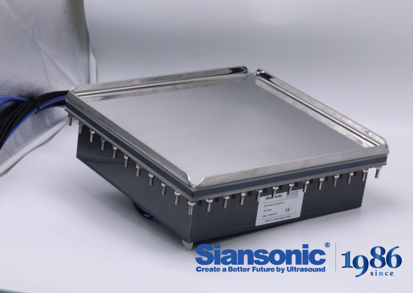
A cleaning tank running at 40 kHz feels powerful, but that aggressive cavitation rarely reaches the final few nanometers without leaving its own marks. The same collapse energy that blasts off larger debris can pit delicate surfaces and create new defect sites. For sub-10 nm particles, the problem is not just force, it is proximity. These particles sit deep inside the viscous sublayer, where bulk liquid motion fades and only the thinnest boundary layer disturbances can exert meaningful drag.
Higher frequencies, typically in the megasonic range from 0.8 MHz to 3 MHz, change the physics entirely. Bubble growth time shrinks, so cavitation becomes less violent but more frequent and far closer to the surface. Acoustic streaming velocity gradients sharpen because the boundary layer thickness scales inversely with the square root of frequency. That thinner layer lets oscillatory flow reach particles that lower frequencies simply glide over. The result is a scrubbing action at the scale of a few nanometers, strong enough to overcome van der Waals adhesion but gentle enough to avoid damage to gate oxides, photomasks, or polished wafers.
There is no universal best frequency, only a narrow process window. On soft or fragile films, 1 MHz and above usually preserves surface integrity while still removing sub-10 nm silica or organic residue. Lower frequencies can still work if power density is reduced or the signal is pulsed, but repeatability becomes difficult once feature sizes drop. The real control comes from pairing frequency with dissolved gas concentration, surfactant chemistry, and surface zeta potential. In practice, engineers tune frequency not to maximize raw cavitation energy, but to place the highest shear rate exactly where the particle sits.
The Hidden Variable: Water Quality in Megasonic Cleaning
In megasonic cleaning, the transducer's energy travels through the liquid medium before it ever reaches the part surface. What that liquid carries matters more than most process engineers admit. Dissolved gases, trace organics, and even the ionic balance of the water can shift cavitation intensity non-linearly. A few parts per billion of surfactant residue, for instance, can dampen the very acoustic streaming you're relying on to dislodge submicron particles.
Water that looks pristine under a turbidity meter may still be loaded with dissolved oxygen or carbon dioxide. These gases act as nucleation sites for cavitation bubbles, changing both their size distribution and collapse energy. The result is often a process that works beautifully on Monday and leaves residue by Wednesday—not because the tool drifted, but because the water chemistry quietly shifted.
Treating water quality as a hidden variable means monitoring it with the same rigor as power density or frequency. Resistivity alone is not enough; you need to track total organic carbon, dissolved gas levels, and particle counts at the point of use. Only then can you separate real cleaning failures from water-borne variability.
Integrating Megasonic Systems Without Disrupting Fab Workflow
Installing megasonic transducers into an existing wet bench often means squeezing new hardware into already crowded tanks. Instead of requiring a full rebuild, look for bolt-on modules that mount to the tank exterior and couple through existing quartz or PTFE walls. This approach preserves the original fluid handling path and keeps the robot's wafer transfer envelope untouched, so adjacent process chambers continue running while the retrofit happens during a scheduled preventive maintenance window.
On the automation side, megasonic generators should speak the same language as the rest of the tool. Using native SECS/GEM or Ethernet-based control lets the megasonic power, frequency, and sweep be stored as recipe variables, not hard-wired settings. Operators can then adjust acoustic energy from the existing GUI without entering the cleanroom, and the fab's host system logs megasonic parameters alongside temperature and chemical concentration. This keeps the workflow identical from an operator's perspective—no extra steps, no new alarms to learn.
Why Some Megasonic Systems Fail on High-Aspect-Ratio Structures
Megasonic cleaning relies on acoustic streaming and cavitation to dislodge particles, but on high-aspect-ratio structures like deep trenches or vias, the physics changes abruptly. The energy that works well on flat surfaces gets trapped or reflected inside narrow openings, creating standing-wave nodes where cleaning action nearly vanishes. As a result, residues linger at the bottom of features while the surrounding areas appear spotless.
Another common failure mode is the collapse of transient cavitation bubbles inside confined spaces. Unlike open baths where bubbles grow and implode harmlessly, a high-aspect-ratio cavity restricts bubble expansion. The resulting asymmetric collapse can generate microjets aimed at sidewalls, causing pattern damage or leaving behind organic byproducts that are even harder to remove than the original particles.
Finally, many systems overlook the impedance mismatch between the cleaning liquid and the feature walls. When acoustic waves enter a deep structure, a portion of the energy converts into shear waves or dissipates as heat, reducing the effective power density at the target surface. Designers often compensate by increasing power, which only worsens damage without improving cleanliness, leading to field failures that are difficult to diagnose after the fact.
Vendor Audit Checklist: From Transducer Materials to Service Contracts
A meaningful vendor audit starts well before the first batch ships. For transducer materials, ask for mill certificates and traceability documents that tie each lot of piezoelectric ceramics, backing compounds, and matching layers to their original production runs. Check whether the supplier stores ceramic elements in humidity-controlled conditions and whether they perform incoming inspection on raw PZT powder—not just final assembly. If they can't show how they control material variation, you'll be chasing sensitivity drift and impedance shifts later.
Move beyond materials to process evidence: bonding thickness, electrode adhesion, and acoustic stack alignment should have defined tolerances with actual measurement records, not just a signed checklist. Then scrutinize service contracts for response-time guarantees, spare transducer availability, and recalibration intervals. A vendor that offers a low unit price but quotes four-week lead times for replacement elements or charges separately for firmware updates isn't saving you anything in a production environment where downtime is measured in hours.
FAQ
Look beyond frequency specs. Actual removal efficiency for sub-100nm particles depends on transducer uniformity, real-time power delivery stability, and how the tank handles gas cavitation without damaging fragile structures. Ask for on-site demo with your actual patterned wafers and measure defect density before/after using a dark-field scanner, not just vendor-supplied data.
Megasonic operates at 0.8-3 MHz versus ultrasonic 20-40 kHz. Higher frequency creates much smaller cavitation bubbles and lower energy release per bubble, so it scrubs particles without ripping off high-aspect-ratio features. But damage still occurs if the transducer produces standing waves or if dissolved gas concentration isn't tightly controlled.
Dissolved O2 and N2 change cavitation threshold and bubble dynamics. Too much gas gives aggressive but uneven cleaning; too little reduces particle removal. Best systems use a degasification module with feedback loop to hold gas concentration within a narrow window, often 1-3 ppm for O2, adjusted per chemistry.
Low-k dielectrics and metal hardmasks are the usual victims. If power density drifts upward, you get sidewall erosion or cap layer loss on porous ULK. If frequency drifts downward, bubble size grows enough to break free-standing MEMS structures. Vendor should provide live impedance monitoring, not just a calibration certificate.
Don't only compare sticker price and chemical usage. Include transducer replacement interval, expected uptime for the generator, DI water consumption per wafer pass, and cost of requalifying after each maintenance event. Some vendors offer predictive maintenance with accelerometer data to extend transducer life beyond 10,000 hours.
Footprint and acoustic isolation are often underestimated. The tank needs a dedicated recirculation loop with bubble traps, and the bench controller must synchronize wafer transfer with ramp-up/ramp-down of acoustic power to avoid exposing wafers during unstable transient. Retrofitting may require a custom tank insert rather than a drop-in module.
Yes, but only at moderate power density (typically 0.3-0.8 W/cm²) combined with a chelating chemistry at pH 8-10. Higher power accelerates copper corrosion at the grain boundaries. The system must also alternate megasonic pulses with fresh chemical dispense to prevent redeposition of silica abrasives.
Request full DOE results showing particle removal efficiency vs. power density and frequency at three different dissolved gas levels, plus SEM cross-sections of the most fragile device structure after 10 cycles. Also ask for log files from an installed base tool running the same chemistry for at least 3 months, with defect maps, not just summary statistics.
Conclusion
Megasonic cleaning is no longer a one-size-fits-all solution for advanced semiconductor fabs. Spec sheets often hide more than they reveal, so engineers must read between the lines: a listed frequency of 950 kHz means little without context on transducer uniformity and power delivery across the entire bath. Frequency choice directly drives sub-10 nm particle removal—higher frequencies tend to be gentler on delicate structures but may sacrifice cavitation energy, while lower frequencies can damage high-aspect-ratio features through transient bubble collapse. Matching the acoustic field to pattern density and geometry is what separates a reliable tool from a yield killer.
Water quality is the hidden variable that undercuts even the best transducer design; dissolved gases, trace metals, and organic residues shift cavitation thresholds unpredictably. Fabs often overlook this when integrating a new system, only to find that batch-to-batch variation stems from upstream DI water chemistry, not the cleaner itself. Seamless integration requires more than a footprint match—it demands real-time monitoring of water resistivity, temperature stability, and acoustic pressure mapping that doesn't interrupt existing wafer flow. Why do some systems fail on high-aspect-ratio structures? Because the standing wave patterns create dead zones or localized hot spots that disaggregate fragile fins or vias. A thorough vendor audit should move beyond glossy brochures to inspect transducer materials, bonding layers, and service contract terms for preventive maintenance and spares. Only then can a fab make a purchase that truly supports high-precision process control.
Contact Us
Contact Person: Ivy Zhang
Email: [email protected]
Tel/WhatsApp: +86 1081502288
Website: https://www.siansonic.com/