

OEM NPT Ball Valve Selection Tips for Reliable Flow Control
2026-11-18
Not every OEM NPT ball valve that fits the thread is fit for the job. Port size, seat material, pressure rating and assembly geometry all shape how smoothly your flow control performs—and how long it lasts under real conditions. Rather than treating the valve as a minor commodity, this guide walks through the selection details that prevent early wear, leak paths and unnecessary pressure drops. If you are sourcing or replacing valves for a demanding fluid system, the right choice starts long before installation. UPTAI brings that practical, engineering-led perspective into focus, so you can match the valve to the system instead of forcing the system around the valve.
NPT Thread Geometry and the Hidden Cost of One Extra Turn
NPT threads don't seal because the flanks fit tightly; they seal because the tapered form crushes the crests and roots together over a narrow band. The taper is roughly 1:16 on diameter, so each additional turn pulls the male thread deeper into the female port and converts rotation into radial expansion. There is a practical limit to how much interference the surrounding material can absorb before it stops behaving like a spring and starts yielding.
One extra turn past the specified wrench engagement often feels reassuring, but it pushes the joint beyond the geometry that the thread was designed to use. On thin-wall ports or cast housings, the added wedging force can crack the boss or permanently stretch the female thread. Even on robust steel blocks, over-tightening squeezes out the sealant and can shear the plating, leaving a metal-to-metal spiral that only needs a small pressure fluctuation to leak.
The hidden cost rarely shows up at the torque wrench. It appears later as a seeping fitting on a Monday morning, a warranty claim on a hydraulic manifold, or a batch of zinc-coated adapters that corrode at the shoulder because the coating was fractured during assembly. Marking the fitting after the prescribed turn count costs nothing, but ignoring the taper's geometry often means paying for the same repair twice.
Material Selection for Wetted Parts Beyond Basic Compatibility Charts
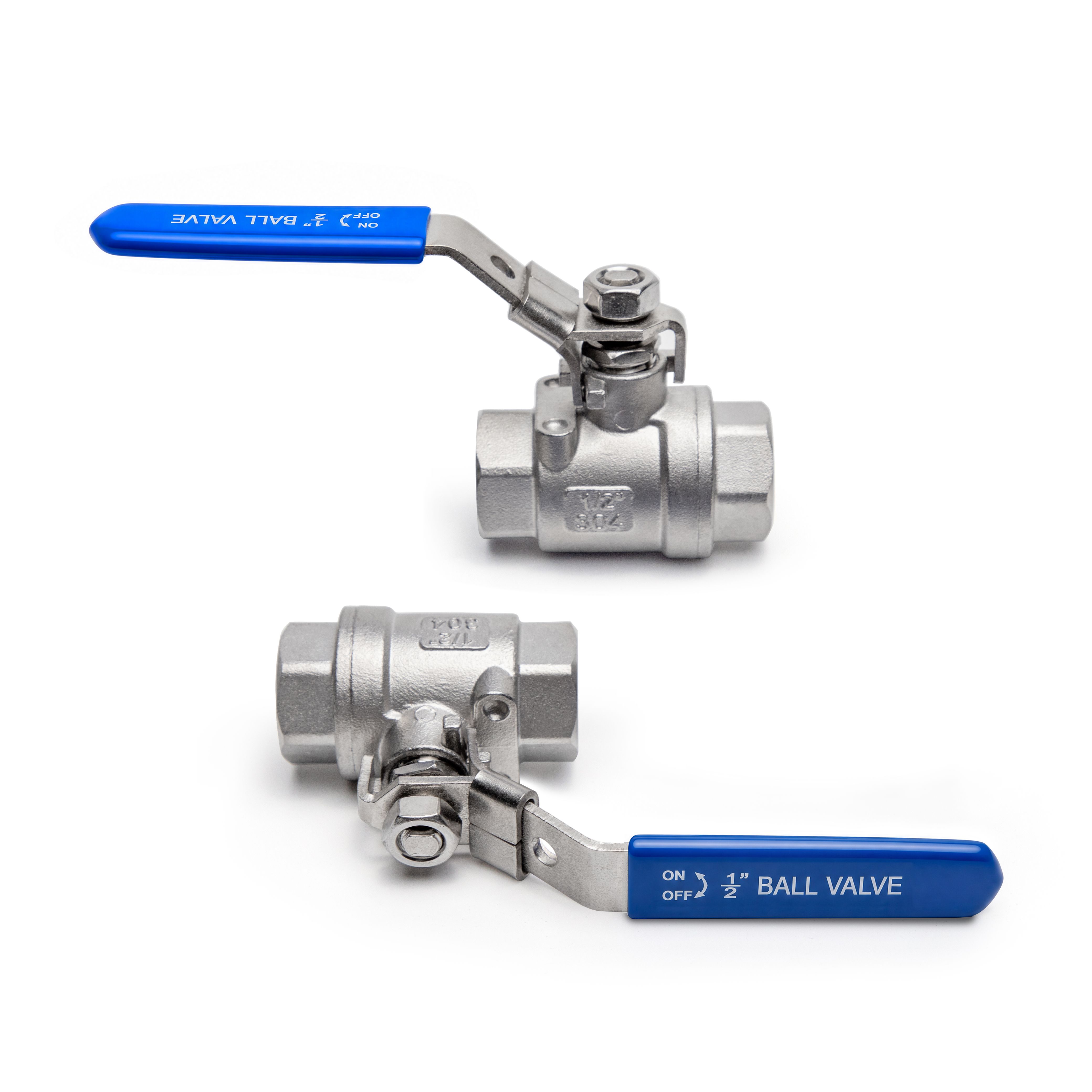
A generic compatibility chart usually captures only static exposure to a single chemical at one or two temperatures. That leaves out how a wetted material behaves when a fluid carries trace contaminants, shifts pH, or cycles between wet and dry conditions. For example, EPDM may tolerate a dilute caustic solution at ambient temperature but can degrade rapidly if the same line is cleaned with steam and a mild acid. The practical question is therefore not simply whether a polymer or alloy resists a listed chemical, but whether it survives the full batch recipe, cleaning sequence, and idle periods.
Mechanical stress changes the picture again. A fluoropolymer liner may show excellent chemical resistance yet crack at weld seams or flange faces because thermal expansion differs from the steel housing. Metals face similar interactions: a 316L stainless pump body can pass a chloride pitting table but fail in a crevice under a gasket when residual stress and low flow allow chloride concentration to build. Small-scale immersion tests with actual process fluid, stressed coupons, or used parts from a similar service tend to reveal failures that charts cannot predict.
Supplier-specific formulation and fabrication history also matter. PVDF from different sources can vary in molecular weight and additive package, which affects weldability and stress crack resistance even when both meet the same grade designation. A material selection should therefore name not just the polymer or alloy, but the acceptable grades, surface finish, joining method, and any post-fabrication treatments. Including these boundaries early avoids late substitutions that quietly reduce the safety margin in wetted service.
Pressure Cycling Behavior That Separates Robust Valves from Marginal Ones
Most valve failures never announce themselves with a sudden crack or a visible leak. They accumulate quietly through thousands of pressure cycles, each one nudging the seal, the seat, or the stem packing a little further out of spec. A robust valve absorbs these micro-deformations without losing its ability to close tightly. A marginal one starts to show its limits early, often as a faint weep at the gland or a rising torque signature long before any operator notices a drop in performance. The real distinction emerges not from catalog ratings but from how the internals respond when the same pressure wave hits them for the ten-thousandth time.
What separates the two is rarely a single material choice. It is the cumulative effect of small structural decisions: how the ball or plug is guided during reversal, whether the seat retainer allows enough flex to recover its shape, and how evenly the body bore distributes stress around the closure member. Robust designs tend to show a stable hysteresis loop in cycle testing, returning to nearly the same sealing force after each depressurization. Marginal designs drift. Their loop widens, their breakaway torque climbs, and eventually the only fix is a rebuild that costs more than the valve itself.
Field data often tells the same story with a different vocabulary. One plant might swap out a cheap trunnion ball valve every eighteen months because it will no longer hold a bubble-tight shutoff on a batch line. Another runs an identically sized valve for a decade on a more punishing cycle count simply because the manufacturer paid attention to bearing placement and seat pocket geometry. That difference is invisible on a cut sheet. It only shows up after the pressure cycles start adding up, and by then the marginal option has already become someone else's maintenance headache.
Balancing Breakaway Torque and Shutoff Tightness in Seat Design
Every valve seat lives between two opposing demands. On one side, the breakaway torque must stay low enough that an operator or actuator can open the valve without excessive force. On the other, the shutoff tightness has to hold line pressure without leaking, which usually means pressing the closure member harder into the seat. Pushing harder raises friction and sticking, so simply increasing seat load is not a real solution.
The geometry of the seat contact area determines how these forces interact. A narrow, sharply defined sealing lip can achieve high local contact stress with moderate overall load, keeping breakaway torque manageable while still meeting tightness requirements. But if that lip is too sharp or too thin, it may deform permanently, groove, or embed debris, causing torque spikes and early leakage. The material pair matters just as much: a slightly compliant seat insert can absorb small misalignments and relax stick-slip tendencies without sacrificing the seal.
Manufacturers tune this balance through controlled interference, seat angle differences, and surface finish. A lapped or polished finish reduces microscopic interlocking that raises breakaway torque, but over-polishing can create a wringing effect similar to gauge blocks. The practical target is a seat design that seals at a modest seating load, releases cleanly without a torque jump, and keeps that behavior across temperature cycles and pressure swings. Testing at low differential pressure often exposes stick-slip that would be hidden at high pressure, so breakaway torque should be verified under conditions closer to actual field operation.
Sizing for Velocity and Recovery Instead of Matching Line Size
Line size often gets copied from the existing header or the nearest connection because it feels like the safe choice. That habit quietly undermines performance. A duct or pipe that simply matches the port diameter can hold velocity in the right range only at one narrow operating point, while every other load condition drifts into settling, excessive pressure drop, or noisy flow.
A more useful starting point is the required transport velocity and what the system needs to recover after each branch or drop. Calculate the cross-sectional area from the actual flow volume at operating conditions, then check that velocity stays high enough to keep particles or condensate moving and low enough to avoid erosion or turbulence-driven losses. Where loads cycle, look at the lowest expected flow as carefully as the peak.
Recovery matters just as much as the initial run. If a trunk line is oversized, pressure or velocity may not rebuild quickly after an offtake opens, and that lag creates uneven delivery. Sizing for stable velocity and recovery usually leads to a different diameter than matching the existing fitting, but it keeps the whole network predictable when demand shifts.
Coatings and Surface Prep That Keep Ball Valves Moving Smoothly
Getting a ball valve to open and close without resistance starts long before it ever goes into service. The metal surfaces inside the body and around the ball are often given a thin, low-friction coating such as electroless nickel or a PTFE-impregnated layer. These finishes do more than add a smooth feel—they reduce the chance of galling when stainless steel parts rub against each other under load. In wet or mildly corrosive lines, the right coating also keeps pitting from turning a clean seal into a leak path over many cycles.
Surface preparation matters just as much as the coating itself. Rough edges, burrs, and leftover machining marks create tiny high spots where friction concentrates first. A well-controlled deburring and polishing step knocks those down before the final treatment goes on. For valves headed into demanding service, a light passivation or chemical cleaning removes oxide films and shop residue, giving the coating a better chance to bond and stay put. The difference shows up later as smoother torque curves and fewer mid-life adjustments.
In field maintenance, the same idea applies to rebuilds and touch-ups. Instead of simply replacing a torn seat or damaged stem, crews that spend time on surface prep usually get longer service from the repaired valve. Cleaning sealing grooves by hand, lightly honing scratched areas, and reapplying a compatible dry-film lubricant to the ball or stem can bring a sluggish valve back to responsive operation without replacing the whole unit. Small prep steps like these often matter more than the brand of seal or the torque setting on the flange bolts.
FAQ
NPT threads are tapered and need some kind of thread sealant or tape to fill the spiral leak path. With OEM assemblies, ask the supplier what they recommend for the specific media and whether the valve body has been pre-treated, because some coatings and lubricants can interfere with sealant adhesion.
If the line velocity is already near the upper limit or the fluid carries solids, a full port keeps the flow path closer to the pipe diameter and reduces turbulence. Standard port valves cost less but create a slight restriction, so they're fine for clean, low-viscosity fluids where a small pressure drop doesn't matter.
PTFE is common but can soften or deform above roughly 180°C depending on load. For higher temperatures or frequent cycling, reinforced PTFE, PEEK, or metal-seated designs usually hold up better, but you need to match the seat to both chemical exposure and the actual operating temperature range, not just peak temperature.
Overtightening is a common cause. NPT fittings seal on thread deformation, and too much torque can crack the valve body or distort the seat pocket. Another cause is mixing thread types or using the wrong sealant. The leak often starts at the thread root or around the stem packing, so checking torque limits and assembly order is worth the time.
Give them the media, normal and upset pressures, temperature range, cycle frequency, pipe schedule, and whether the valve sits in continuous or intermittent service. Also mention vibration, exposure to cleaning chemicals, and any certification needs. That combination usually changes material and stem packing choices more than the basic NPT size does.
Most ball valves are designed for on/off or isolation duty. Using them for throttling can erode the ball and seats, especially with abrasive fluids or high pressure drops. If you need actual flow control, request an OEM valve with a characterized ball or a separate control valve, and avoid using a standard ball half-open for long periods.
Body material matters as much as the seats and seals. Stainless steel resists many chemicals but can still pit in chloride-rich environments, while brass or bronze may be cheaper but degrade with acids or ammonia. Have the supplier verify wetted materials against the full chemical mix, including trace impurities, because the body can fail even when the seat survives.
The pressure rating drops as temperature rises, so the cold working pressure alone is not enough. Check the pressure-temperature curve for the body, stem seal, and seat material together. A valve rated for 1000 psi at room temperature may only be good for a few hundred psi at 150°C, and the weakest component usually sets the limit.
Conclusion
NPT threads look forgiving until a single extra turn changes the stress pattern inside the valve body. That extra engagement does not usually improve sealing; it can stretch the female port, distort the seat pocket, and shift the ball position enough to raise operating torque. For OEM builds, checking thread depth and using a controlled thread sealant procedure often matters more than chasing a higher pressure class. The same understated logic applies to wetted materials. A compatibility chart may show that a stainless ball and PTFE seat survive a chemical, but it rarely captures how the pairing behaves after thermal swings or repeated cycling. Nylon, PEEK, and reinforced PTFE seats each respond differently once the valve sees pressure spikes rather than steady flow.
Pressure cycling separates durable designs from marginal ones fairly quickly. A body that passes a static hydro test can still develop weep at the stem or end connections after thousands of low-amplitude cycles, so looking at fatigue behavior in the body-to-end joint and stem seal is worth the effort. Seat design then forces a trade-off: softer seats lower breakaway torque but may sacrifice shutoff tightness after wear, while harder seats hold a seal longer but feel stiff from the start. Sizing should focus on velocity and pressure recovery rather than simply matching line size, since an undersized valve can create cavitation-like instability and an oversized valve wastes energy. Finally, surface prep and coatings such as electroless nickel or hard chrome on the ball and stem reduce galling and keep the valve moving smoothly over time, especially in dry or abrasive service.
Contact Us
Contact Person: Adonis
Email: [email protected]
Tel/WhatsApp: 8615858822657
Website: https://www.uptaivalve.com