

OEM Type B RCD Key Considerations for Safe Electrical Design
2026-10-10
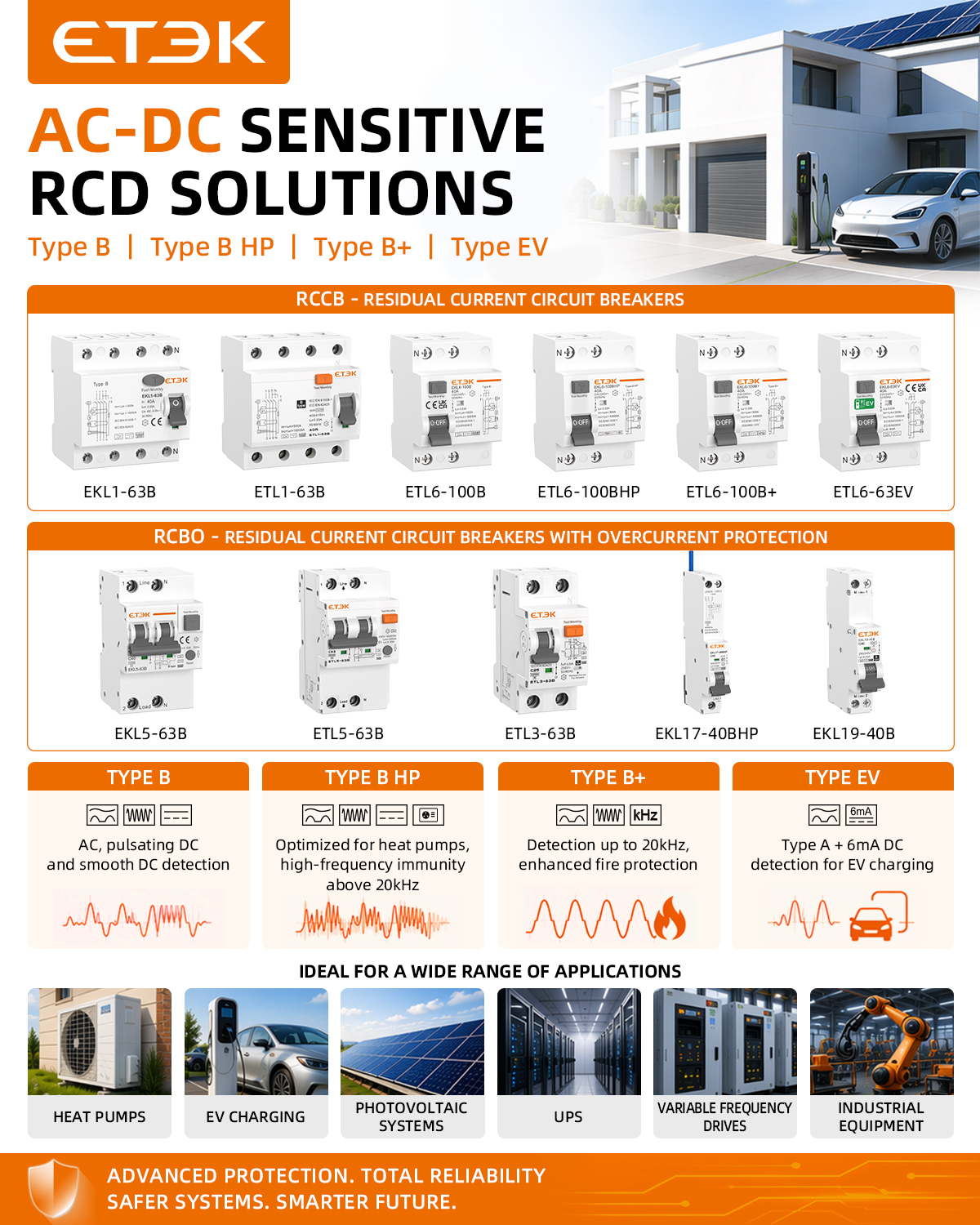
Every OEM design engineer knows the sinking feeling of a prototype that trips on nuisance leakage—or worse, doesn’t trip when it should. Type B RCDs promise protection against AC, pulsating DC, and smooth DC residual currents, but integrating them safely demands more than reading a datasheet. This guide from ETEK walks through the critical design choices that separate robust electrical systems from field failures.
The DC Residual Current Blind Spot in Standard Protection
Standard residual current devices are typically designed around AC current transformers, which means they respond to alternating fault currents but offer little to no response when a direct current fault appears. A DC residual current, whether originating from a rectifier, battery bank, or certain power electronic loads, can saturate the transformer core or fail to induce the necessary secondary signal, leaving the circuit unprotected.
This blind spot becomes more serious as modern installations increasingly combine AC and DC circuits. Without a dedicated Type B or B+ residual current device, a DC leakage path can persist undetected, and even a relatively small direct current can gradually impair the sensitivity of an upstream AC RCD. The result is a protection system that appears fully functional but may fail to trip at the critical moment.
Selecting Trip Sensitivity for the Actual Load, Not the Nameplate
Circuit breakers are often sized from the motor nameplate, but the actual running load can be considerably lower, especially in applications where the driven equipment rarely reaches full rated current. If you set the trip sensitivity based solely on the nameplate value, you may end up with a breaker that allows damaging overloads to persist because the real current stays below the nameplate threshold while still overheating windings or cables. A better approach is to measure the true load profile over a representative operating cycle, then set the thermal or electronic trip unit to protect that running current with a reasonable margin, not the idealized maximum.
This difference shows up clearly in fans, pumps, and conveyors where the motor may be intentionally oversized for future expansion or because the original design assumed worst-case conditions. For instance, a 100 hp motor on a fan might draw only 62 hp during normal operation. Setting the overload at 125% of the nameplate current would allow continuous operation at a level that could damage insulation over time. Instead, by logging actual amperage, you can set the trip closer to, say, 110% of the measured running current, which still avoids nuisance trips but catches genuine overcurrent conditions early.
Some maintenance teams worry that tightening the trip setting will cause nuisance tripping during startup or transient loads. The key is to use the breaker's time-current characteristics properly. A motor starting current may briefly exceed the trip setting, but modern electronic trip units can be programmed with a short-time delay or use an I²t curve that permits inrush without sacrificing protection for sustained overloads. Once you shift your reference from the nameplate to the observed load, you close the gap between what the breaker allows and what the equipment can really handle, reducing both unplanned downtime and long-term thermal damage.
Wiring Layout Choices That Quietly Undermine Protection
A surge protector’s clamping voltage looks great on paper, but if you mount it six inches from the panel with loose, untwisted leads, you’ve added enough series inductance to nullify most of the protection. Every inch of unpaired conductor contributes roughly 15–20 nH of inductance; during a 10 kA, 8/20 µs surge, that can produce hundreds of volts of let-through right at the protected load. Twisting the leads or using a close-coupled Kelvin connection costs nothing, yet it’s often skipped because the layout still looks neat in the enclosure.
Another quiet culprit is the shared return path. In many control panels, “protected” circuits are grounded to the same neutral or reference busbar as unfiltered loads like motors, VFDs, or solenoids. When those devices inject harmonic or switching currents into the bus, the resulting voltage drop appears across every connected ground reference. That common-impedance coupling gives your sensitive controller a dirty reference even though each branch has its own circuit breaker. Running a dedicated return conductor from the protected circuit back to the single-point ground, instead of daisy-chaining through the main bus, removes this subtle undermining.
Cable routing matters just as much. Placing a shielded analog sensor cable directly alongside a 480 V feeder in the same tray for fifty feet creates mutual inductance and capacitive coupling. Even with the shield grounded, currents induced in the tray’s metallic structure can flow along the signal return, injecting common-mode noise that the input filter struggles to reject. Crossing power cables at right angles, or keeping at least twelve inches of separation for low-level signal lines, is a layout choice that doesn’t increase bill of materials but is routinely ignored when trays get crowded.
Environmental Drift in Residual Current Thresholds
The baseline for residual current detection rarely stays fixed once equipment leaves the calibration bench. Temperature swings, moisture ingress, and slow accumulation of conductive dust shift the tripping point in ways that are easy to overlook until a nuisance trip or a missed fault brings them into focus.
Drift isn't always linear. A cold start can tighten the threshold because lower temperatures increase the effective resistance of some sensing elements, while sustained humidity can create leakage paths that effectively desensitize the detector. Over months, these effects compound with component aging, so the original margin between normal leakage and the safety cutoff narrows or widens depending on site conditions.
For installations where nuisance tripping is already a problem, tracking threshold drift against local weather and load cycles often reveals patterns that static commissioning data misses. Simple periodic measurements under known residual current levels give a practical way to separate reversible environmental influence from permanent degradation.
Field Verification Beyond Type Test Certificates
Type test certificates offer a snapshot of performance under controlled laboratory conditions, but they rarely capture the reality of an installation. Field verification goes further by examining how equipment behaves in its actual operating environment—accounting for variables like voltage fluctuations, harmonics, grounding quality, and ambient temperature swings that certificates simply cannot replicate. This on-site scrutiny often uncovers subtle deviations that, while absent from the datasheet, materially affect safety margins and long-term reliability.
One practical approach is to combine visual inspection with live measurement. For example, thermal imaging during peak load can reveal hotspots caused by loose connections or unbalanced phases, even when the device passed its type test years earlier. Similarly, power quality analyzers logged over several days may expose transient overvoltages or harmonic distortion that push components beyond their certified envelope. These field findings guide targeted corrections—retorquing, phase rebalancing, or adding filtering—that a paper certificate would never prompt.
Beyond catching immediate risks, documented field verification builds a performance baseline for future maintenance. Instead of relying on generic intervals from the manufacturer, asset owners can compare periodic field measurements against the initial verified state. This closes the loop between design assumptions and operational truth, making type test certificates a starting point rather than the last word on equipment integrity.
Coordinating Upstream and Downstream Devices Without Losing Sensitivity
Sensitivity usually takes a hit the moment you chain one device to another, because each added stage brings its own input capacitance, bias currents, and ground loop potential. The trick is not to fight those effects with brute amplification, but to stop them before they eat into the signal. That means keeping the upstream output stage low impedance while giving the downstream input enough headroom to handle voltage spikes without clipping, and matching the time constants so no stage acts as an unintentional high-pass or low-pass filter.
A more workable approach is to treat the connection as a negotiated interface rather than a fixed one. Selectable input ranges, AC/DC coupling choices, and isolated power rails let you adjust for whether the upstream device is a sensor, a transmitter, or another controller. On the firmware side, periodic auto-zeroing and per-channel offset correction can remove drift introduced by the link itself, so the downstream detector doesn't have to be desensitized just to ignore the connection noise.
What works in practice is to preserve a window of usable signal instead of chasing the lowest possible noise figure. With proper termination, a modest bias margin, and active impedance matching on the receiving end, a string of coordinated devices can pass along subtle changes without drowning them in artifacts. The result is clean triggering at the far end, fewer false events, and a sensitivity level that stays consistent no matter how many upstream stages sit in front of it.
FAQ
A VFD can generate smooth DC residual currents under certain fault conditions. Type AC devices only respond to sinusoidal AC residuals, so they may not trip when a DC fault occurs. Type B detection covers AC, pulsating DC, and smooth DC, which makes it suitable for circuits with rectifiers or inverters.
Type B+ extends the frequency range for AC residual current detection beyond the typical 50/60 Hz, often up to 20 kHz. This matters in OEM machinery with high-frequency switching or harmonics. Type B is adequate for many DC-capable circuits, but B+ provides additional protection against high-frequency leakage.
Place it at the supply side of the relevant branch circuit, but after any equipment that generates high inrush currents or EMI filters that might cause transient leakage. Keep cable runs between the RCD and protected equipment as short as possible and avoid bundled neutral and earth conductors to reduce capacitive coupling that can trigger false trips.
Yes, a 30 mA Type B RCD is generally suitable for additional protection against electric shock, including circuits with DC components. However, you should verify that the total expected leakage current, including filter capacitors and motor cable capacitance, stays well below the trip threshold, otherwise nuisance tripping will interrupt production.
Long shielded motor cables increase earth leakage current due to capacitance between conductors and screen. If the leakage approaches the RCD threshold, you may need a higher rated residual current for fire protection only, or use a separate RCD per drive, or add common-mode chokes to reduce leakage instead of simply increasing the trip level.
The RCD must be coordinated with the upstream breaker or fuse to ensure it does not have to break fault currents beyond its rated short-circuit capacity. The overcurrent device should clear high-level short circuits, while the RCD handles residual current faults. Check the conditional short-circuit rating and the maximum permissible back-up protection specified by the RCD manufacturer.
Yes, but you must ensure that the transformer secondary is not left floating. A Type B RCD needs a reference to earth on the supply side to measure residual current. If the secondary is isolated, a first earth fault may not produce enough residual current to trip the RCD. In that case, consider an insulation monitoring device instead.
Use a dedicated RCD tester that can simulate smooth DC and pulsating DC residual currents, not just a standard AC tester. During commissioning, test at the actual operating temperature and with the machine running under load, because some RCDs may behave differently when warm or when high-frequency noise is present.
Conclusion
Type B RCDs often get treated as a drop-in safety upgrade, but OEM machinery tells a different story. Standard Type A units cannot respond to smooth DC residual currents produced by rectifiers or variable-speed drives, leaving a blind spot that only a genuine Type B design can cover. Yet the choice of trip sensitivity matters just as much as the device type. Using the nameplate current as a guide often misses the true leakage profile: harmonic-rich loads, ageing insulation, and long motor cables can push actual residual current well above nominal values, so the RCD must be set for the real operating load, not the label. Wiring layout can quietly undermine all of this. Long runs, tight bundling, or poorly separated power and signal cables introduce capacitive coupling that diverts fault current away from the sensor, effectively reducing the RCD’s sensitivity at the point where protection is expected.
Environmental drift adds another layer of uncertainty. Temperature swings, humidity, and conductive dust gradually shift residual current thresholds, so a device that passes a clean type test may behave very differently in the field. Relying on certificates alone is not enough; commissioning should include verification under actual load steps, motor starts, and normal supply noise. Finally, coordinating upstream and downstream devices without sacrificing sensitivity calls for more than just picking a time-delayed unit. Selective RCD settings must be matched to the real earth leakage signature of the installation, otherwise the system either fails to trip on a genuine fault or loses discrimination when it matters most. In practice, safe electrical design with Type B RCDs means accounting for DC fault behaviour, realistic trip levels, wiring discipline, environmental margins, and verified coordination—not simply ticking a box on a specification sheet.
Contact Us
Contact Person: Andy
Email: [email protected]
Tel/WhatsApp: +86 13356133008
Website: https://www.etek-china.com/