

Sliding Head Lathe Factory Guide to Precision Turned Parts
2026-09-01
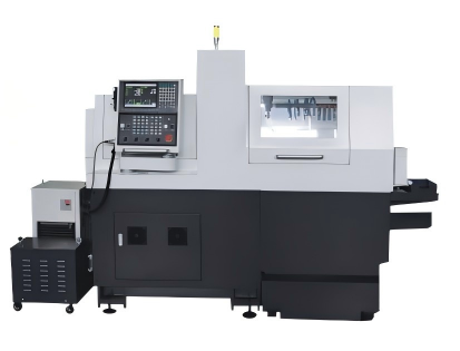
Most buyers assume all turned parts are the same—until a batch arrives with burrs, off-spec tolerances, or a surface finish that wrecks assembly. The guide to precision turned parts from a real sliding head lathe factory changes that. It walks through what actually matters: tooling strategies, material behavior, in-process control, and why Swiss-style machining wins on small, complex geometries. We wrote it from the floor at WINNRUI CNC, not from a marketing deck. If you're sourcing shafts, pins, connectors, or miniature screw machine parts, the next ten minutes could save you a supplier audit.
The Real Reason Swiss Lathes Dominate Small Parts
Swiss lathes didn't earn their reputation by accident. The sliding headstock design lets the bar stock move while the tool stays fixed, so the cutting happens right next to the guide bushing. That means a long, skinny part never gets a chance to flex or chatter the way it would on a conventional lathe. Once you've watched a 0.5 mm diameter pin hold a tight tolerance over a 40 mm length, it's hard to go back.
Beyond rigidity, there's the matter of done-in-one efficiency. Because the part is supported so close to the cut, Swiss machines can turn, drill, thread, and mill in a single setup without constant repositioning. That removes stack-up errors and lets shops run lights-out with far less babysitting. For small parts where seconds per piece matter, this isn't just a convenience — it changes what's actually profitable to quote.
But the deepest advantage may be thermal stability. The cutting zone is tiny, chips clear quickly, and the spindle doesn't wander as it heats up. Over thousands of parts, that consistency is what separates a good batch from scrap. Machinists don't always talk about it, but they feel it when they check the tenths in the morning and find them right where they left them the night before.
Bar Stock Selection Mistakes That Show Up in Final Inspection
One of the stealthiest bar stock selection errors is grabbing a free-machining grade when the print calls for a hardened alloy. The shop floor might not notice the difference during turning or milling—chips look similar, feeds stay stable—but the final inspection bench tells another story. A quick Rockwell test comes back ten points low, and the spectro analysis confirms the mix-up. Now the entire batch sits in quarantine, and the cost isn't just the material; it's the lost spindle hours and the rush to re-quote for the correct 4140 or 4340.
Dimensional callouts on raw bar stock rarely get the scrutiny they deserve until the finished part fails a CMM check. A bar that's a couple thousandths over nominal or bowed by half a millimeter can slide through incoming QC, especially when operators trust the mill cert instead of measuring. The error surfaces late: turned journals run eccentric, bores drift off center, or a keyway depth varies beyond tolerance. By the time final inspection flags the issue, the only fix is scrapping the lot or attempting a desperate salvage operation that rarely satisfies the customer.
Internal defects in bar stock are the quietest killers of a production run. Laminations, seams, or non-metallic inclusions hide beneath the surface, invisible to the eye and often untouched by a quick incoming diameter check. The part machines beautifully, passes first-article, and then fails magnetic particle inspection at the very end—fine cracks bloom along a cold-worked edge or a stress riser reveals a slag line. Rework isn't an option, and the root cause traces back to a supplier lot that should have been ultrasonic tested before it ever hit the saw.
Guide Bushings: The Tiny Component That Makes or Breaks Straightness
Guide bushings rarely get the attention they deserve. Tucked inside the machine, they do the quiet work of keeping a drill or reamer on its intended path from the very first engagement. When a bushing is worn, out of round, or slightly misaligned, the tool doesn't just start off-center—it tends to wander further as the hole deepens. That's why a seemingly tiny clearance issue can turn a straightness tolerance from easy to impossible.
The mechanics are straightforward but unforgiving. A guide bushing supports the tool shank near the workpiece, constraining its radial movement during entry. Any gap between the bushing ID and the tool OD allows the tip to deflect. As the tool advances, that initial deflection becomes a directional bias. It doesn't correct itself. The deeper you go, the more the hole drifts, and no amount of pecking or dwell will pull it back. Material hardness, bushing length, and lubrication all play supporting roles, but the bushing's own precision is the main actor.
So if you're fighting straightness issues and the machine geometry checks out, take a hard look at the guide bushing. Measure the clearance with a pin gage, not just by feel. Check runout with the bushing installed and the spindle turning. Even a few tenths of a thousandth of an inch of sloppiness can push a hole out of tolerance over several diameters of depth. Replacing bushings on a schedule, before they look visibly bad, is often the cheapest way to keep straightness where it belongs.
What Your Setup Sheet Reveals About a Shop's True Capability
A setup sheet is rarely read for what it omits. When a shop lists only nominal dimensions and tool numbers but skips over datum references, chip evacuation notes, or the order of operations for re-cuts, that silence speaks volumes. It points to a team that may be able to run a proven job, but cannot yet articulate why the process works. In contrast, a sheet that documents non-obvious choices—like a deliberate offset to account for thermal drift, or a note to check concentricity after the third part—signals that someone on the floor has already learned the hard lessons and written them down so the next person does not have to.
The depth of a setup sheet also reveals how a shop handles variation. A sheet that includes expected load meter readings, torque values for fixture bolts, and the specific probe routines for in-process verification tells you the shop is not relying on memory or heroics. It means the process has enough structure to survive a shift change or a new operator. Many shops claim they can hold tight tolerances; fewer can show you the exact clamping sequence and tool stick-out lengths that make those tolerances repeatable day after day.
Finally, look at what happens after the first article. If the setup sheet has a section for recording actual measured values and any adjustments made during prove-out, that shop treats the first part as data, not destiny. They are building a record that separates a one-time success from a controlled capability. That distinction is what separates a shop that occasionally gets lucky from one that can consistently say yes to difficult work.
Tool Wear, Thermal Drift, and Other Tolerance Killers
Every machinist eventually learns that the blueprints lie. The dimensions on the page assume a perfect world where cutting edges never dull, spindles never warm up, and gravity doesn't pull on a 500-pound fixture. Out on the floor, those assumptions collapse the moment a tool touches metal. The real battle isn't hitting the nominal number once—it's holding that number through eight hours of heat, vibration, and cumulative wear. Those silent forces eat away at your tolerances while you're busy checking the readout.
Tool wear is the most obvious offender because you can see it under a microscope, but the damage starts long before you notice a difference in the finish. A tiny rounding of the cutting edge changes how the tool deflects under load, and that deflection shifts your feature location by a few tenths. Thermal drift is sneakier. The spindle housing expands as it warms up, the ballscrews grow a couple microns, and suddenly the machine's coordinate system has drifted from where it was during the morning warm-up cycle. You adjust for one, and the other bites you from a different direction.
Then there are the tolerance killers nobody writes on the setup sheet: backlash in a worn thrust bearing, a coolant nozzle knocked slightly off target, a pallet that doesn't seat exactly the same way twice, thermal expansion of the part itself as it sits in the fixture after a heavy roughing pass. None of these show up in a spreadsheet. The machinists who consistently hold tight tolerances aren't just better programmers—they've learned to anticipate how the machine, the tool, and the workpiece all shift over time, and they compensate before the CMM reports another red number.
Inside the Sub-Spindle Handoff: Where Scrap Parts Are Born
The sub-spindle handoff looks straightforward, but it’s where a lot of finished parts turn into scrap. Both spindles have to line up within a few microns while running at matched speeds and gripping with consistent drawbar pressure. If the spindle noses are even slightly out of coaxial alignment, or if one chuck closes a fraction of a second too early, the part gets cocked, scored, or dropped. Those tiny errors rarely show up at the control panel, but they show up clearly on the rejected parts tray.
Thermal growth works against you all shift long. The machine geometry you dialed in at 8 a.m. won’t match the geometry at 2 p.m. after the castings have warmed up. Chips and coolant residue on the collet faces add another layer of runout, and the transfer position often relies on a dead stop that wears over months of use. That wear shifts the clamp point just enough to bend thin-walled parts or leave jaw marks on a surface that was supposed to be finished already.
The sub-spindle typically grabs an already machined diameter, so any small burr, taper, or mismatch in gripping size gets amplified right at the moment of transfer. People often blame the insert, the material, or the program when a batch goes bad, but the real cause is usually a handoff misalignment that nobody measured under load. Checking static alignment isn’t enough; you need to indicate both spindles while they’re actually gripping a part, otherwise you’ll keep chasing ghost scrap.
FAQ
The bar stock moves through a guide bushing while the cutting tools advance, so the workpiece is always supported close to the cutting zone. That arrangement reduces deflection on long, slender parts and allows aggressive feeds without sacrificing surface finish.
Brass, aluminum, stainless steel, titanium, and engineering plastics like PEEK are all common. Free-machining grades cut cleaner, but a well-tuned sliding head machine can handle tough alloys if the tooling and coolant are chosen carefully.
Most shops quote ±0.0002 inches on diameter without much trouble, and tighter on critical features if the batch and setup justify it. The guide bushing setup makes this repeatable, but real capability depends on material, tool wear, and thermal stability.
Those sectors need tiny, intricate parts with long length-to-diameter ratios, like bone screws, connector pins, or nozzle tips. A sliding head lathe keeps the bar stable during the cut, so you get clean details and fewer secondary operations.
They match the guide bushing clearance to the bar diameter, use high-pressure coolant to clear chips, and often run the spindle at speeds that keep the cutting edge engaged properly. Sometimes a synchronized sub-spindle pulls the part to reduce whip.
Look at their inspection reports for similar part families, ask about how they handle bar feeding and remnant control, and see if they have live tooling and sub-spindle experience. A shop that only does simple bushings may not be ready for complex medical or aerospace work.
Yes. Most modern sliding head lathes have live tooling stations on the gang slide or turret, plus a sub-spindle for back-working. That means you can mill flats, drill cross holes, and thread the back side without moving the part to another machine.
In-process probing, automatic bar loaders, and tool life monitoring handle most of it. The guide bushing setting is checked at the start of each batch and adjusted as the bar diameter varies, so dimensions stay stable from first part to last.
Conclusion
Most shops assume a sliding head lathe earns its keep through cycle time alone, but the real edge shows up in how the machine supports the bar so close to the cut. That short unsupported span is why diameters stay consistent on long, slender parts and why a worn or misaligned guide bushing can silently wreck straightness before the operator notices. Bar stock choices matter just as much: oversized or out-of-round stock drags through the bush, burns tools, and leaves chatter marks that only surface at final inspection. Turned parts from a Swiss machine are never just “machined” — they survive or fail based on stock prep and bushing condition.
A shop’s setup sheet says more than the print does. If the sheet lists only offsets and tool numbers, you’re looking at guesswork. A better sheet records bushing clearance, stock tension, cutting speeds, and handoff timings, because those are the variables that keep tolerances alive. Tool wear and thermal drift creep in slowly; carbide edges dull, spindles warm up, and suddenly a ±0.005mm feature drifts outside spec between morning and afternoon. The sub-spindle handoff is where most scrap hides — parts get dropped, pushed off-center, or cut short when the main and sub don’t agree. Factories that hold tight work treat that handoff as a controlled operation, not an afterthought.
Contact Us
Contact Person: Tim
Email: [email protected]
Tel/WhatsApp: +86 15522553731
Website: https://www.winnrui-cnc.com/